 |
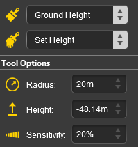
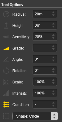
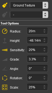
| Radius |
the brush radius (metres) - see Notes: below |
|
|
| Sensitivity |
texture transparency |
| Range: |
1% = almost transparent to |
| |
100% = solid (opaque) |
|
| Rotation |
initial rotation angle - see Notes: below |
| Range: |
0° to ±360° (larger angles can be entered) |
|
| Scale |
the texture pattern scaling factor |
| Range: |
0.01% = smallest to 100% = full size |
|
|
|
| Steps: To paint a Ground Texture:- |
 |
select your ground texture in the Assets Palette |
 |
select the Brush Tool from the Tools Palette |
 |
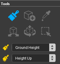
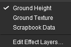
select the Ground Texture target from the Brush drop down menu |
 |
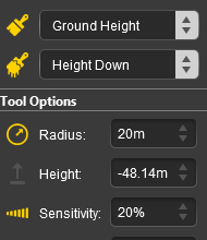
set the brush controls (radius, sensitivity, rotation, scale) in the Tool Options Palette |
 |
Left Click and Drag on the terrain to paint with the texture |
|
|
 |
Notes:
|
| Error creating thumbnail: /bin/bash: line 1: /usr/bin/convert: No such file or directory Error code: 127 |
Unlike Surveyor Classic, there is no upper limit to the brush Radius . Brushes of hundreds of metres (even kilometres) in size are possible. However, the performance will decrease as the brush radius increases. If you are using the brush to paint an entire baseboard, or many baseboards, then the Marquee Tool will be quicker but it will not give the options of changing the scale and rotation. |
| Error creating thumbnail: /bin/bash: line 1: /usr/bin/convert: No such file or directory Error code: 127 |
The Rotation controls the starting angle for the texture when painting and is often used to avoid pattern repetition. As in Surveyor Classic, holding down the [ or ] keys while painting will continuously change the rotation angle.
 |
Warning: Changing the rotation angle during painting is not recommended for PBR Textures as this will significantly increase the memory useage (each rotation will load in another copy of the PBR texture). |
|
|
|
When a new baseboard is added it will be covered with the Default ground texture for the selected Region. This can be temporarily disabled or permanently changed to a different texture (including to the standard TRS19 grid pattern).
 |
The easiest option is to disable the current default ground texture
Steps: |
|
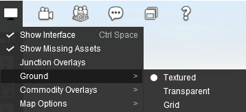
open the Interface Menu |
|
select the Ground option |
|
select the Grid option. This will use the current grid texture. |
|
|
A more permanent but more complex solution is to edit an existing Region asset or create one of your own to add your preferred ground texture (such as the standard TRS19 grid pattern) to each new route you create and every new baseboard that you add.
 |
Information on creating and editing Region assets can be found on the Trainz Wiki at:-
|
Scrapbook Data
This brush tool uses both the Tool Options Palette and the Scrapbook Palette. If these palettes are not visible on the screen then refer to  Notes: Palettes at the top of this document. |
|
 |
The scrapbook contents can be Pasted into a route from the Context Menu of a scenery asset. |
|
The Scrapbook Brush
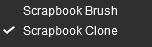
When the Scrapbook Data Target is selected, the second drop down box will give a choice of two actions.
|
The choices are:- |
 |
Scrapbook Brush |
|
Scrapbook Clone |
|
 |
Notes:
|
| Scrapbook Brush will resize the scrapbook contents to fit the selected brush shape and size.
|
| Scrapbook Clone will paste the scrapbook at its original size - subject to the Scale setting.
|
|
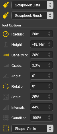
| The available brush tool options are shown in the Tool Options Palette with a Gold coloured icon next to their names. Those options that have their icon greyed out will be ignored, but they can still be edited. |
Scrapbook Brush
 |
Scrapbook Clone
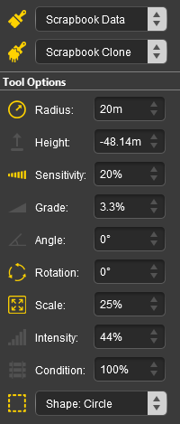 |
| Radius |
the brush radius (metres) - see Notes: below |
|
|
| Rotation |
initial rotation angle (degrees) - see Notes: below |
| Range: |
0° to ±360° (larger angles can be entered) |
|
| Scale |
the scrapbook scaling factor |
| Range: |
0.01% = smallest to 100% = full size |
|
| Shape |
brush shape |
| Options: |
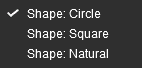 |
Circle and Square will set the brush to the selected shape |
| |
Natural will set the brush to the same shape as the Marquee that created the scrapbook, which may be rectangular. The Radius setting will set the relative brush dimensions |
|
|
|
|
Notes:
|
|
|
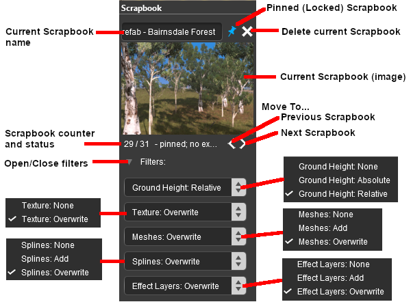
The Scrapbook Palette
 |
|
Scrapbook Pasting Options |
| What Features to Paste |
| |
Ground Height |
terrain height(s) used in the scrapbook |
| |
Texture |
textures used in the scrapbook |
| |
Meshes |
scenery objects (e.g. trees, buildings) used in the scrapbook |
| |
Splines |
spline objects used in the scrapbook |
| |
Effect Layers |
effect layers (TurfFX, Clutter) used in the scrapbook |
| How to Paste Each Feature |
| |
None |
do not paste this feature |
| |
Add |
add this feature to those already present |
| |
Overwrite |
use this feature to replace those already present |
| For the Ground Height feature:- |
| |
Absolute |
use the ground heights in the scrapbook to replace the existing ground heights |
| |
Relative |
modify the existing ground heights according to those used in the scrapbook (to ignore the scrapbook ground heights completely select the option None) |
|
|
Effect Layers
If the route has preset Effect Layers installed then they will be listed individually as additional Targets.
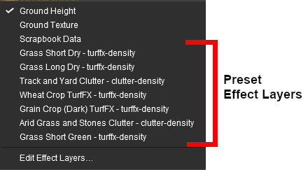 |
To paint with an Effect Layer simply select one from the list and start painting. The Brush Tool Options settings Radius and Sensitivity will control how the Effect Layer is applied.
|
Notes:
|
|
|
|
Edit Effect Layers...
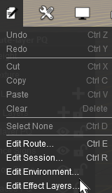
When this Target is selected, the Edit Effect Layers options will appear. This is the same as selecting Edit Effect Layers ... from the Trainz Edit Menu.
 |
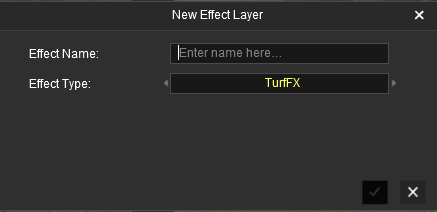
- If no Effect Layers are present then you can create a new one
 |
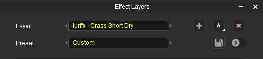
- If Effect Layers are present then select one to edit
 |
|
Effect layers are created for each route. You can select and edit a previously saved Effect Layer Asset rather than having to recreate the entire effect each time. |
|
|
More information on creating and editing Effect Layers can be found on the Trainz Wiki at:-
|
 |
Keyboard Shortcut: E |
The Placement Tool adds objects to a route |
| This tool uses the Assets Palette. If this palette is not visible on the screen then refer to Notes: Palettes at the top of this document.
|
|
The Placement Tool has no drop down menu lists.
The first step is to identify and select the particular object that you want to add to the route.
Placing a Scenery Mesh Object
Individual "non-spline" scenery objects that are not attached to track are often referred to in Trainz terminology as Scenery Mesh Objects .
Steps: To add a Scenery Mesh Object the first step is to identify the exact object you want to add.
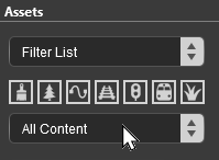
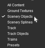
In the Asset Palette either:-
|
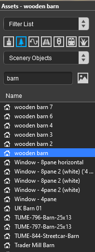
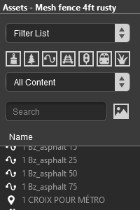
To narrow down the filter list type part of the object name into the Search Text Box. For example if you have selected Scenery Objects and want to find "barns", then type "barn" (UPPER/lower case does not matter). |
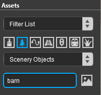 |
This will list all the Scenery Objects containing the text "barn" in their name.
|
| The final step is to place the selected object into the route. |
- If the Placement Tool is not selected then Left click it or press the E key
- Click on the spot where you want to place the object
|
|
|
Notes:
|
|
|
|
Placing a Scenery or Track Spline
Start the process of laying a track or spline by identifying and selecting the track or scenery spline as described in steps to in Placing a Scenery Mesh Object above but in Step select the Scenery Spline or the Track filter in the Assets Palette
|
| Select from the Assets Palette object icons:- |
 |
spline scenery objects |
OR |
 |
track spline objects |
|
|
|
OR |
| Select from the Assets Palette object drop down list:- |
| Scenery Splines |
OR |
Track |
|
|
|
Then continue with the steps listed below:-
Spline Segment Heights
When you start adding a spline to a route it will always be placed at the height of the terrain regardless of the Tool Options Height setting.
However, you can set the height of the last segment that was added and this will set the height of all the segments added from that point.
| Steps: To set the height of a Spline:- |
|
Lay the first spline segment which will be added at the terrain ground height |
|
Enter a value in the Tool Options Height and press the Enter key |
| The endpoints of the current spline segment will immediately be adjusted to the new height setting |
|
Continue laying spline segments. Each new segment will be added at the new height
|
|
Placing Track Objects
Track Objects are assets, both visible and invisible, that can only be attached to track splines.
|
Notes:
|
|
|
Start the process of adding a track object by identifying and selecting the object as described in steps to in Placing a Scenery Mesh Object above but in Step select the Track Object filter in the Assets Palette
Select from the Assets Palette object icons:-
 Track objects |
|
|
OR |
Select from the Assets Palette object drop down list:-
Track Objects |
|
|
Step  Left click on the track segment at the position where you want to place the track object. |
|
The Tool Options Palette Height setting for Scenery Mesh Objects, Scenery Splines, Track Splines and Track Objects when using the Placement Tool does not show a gold coloured icon which indicates an "active" control setting but the setting is active.
Scenery and Track Mesh Object Tool Options
Spline (Scenery and Track) Tool Options
Splines have two Placement Tool settings in the Tool Options Palette.
|
Notes:
|
| |
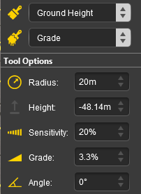
The Grade is defined as vertical rise divided by horizontal distance converted to a percentage figure. So a grade of 100% (the maximum allowed) would mean a gradient formed by both measurements having the same value (e.g. a rise of 50m over a distance of 50m). A vertical grade (such as up a cliff face) would have an infinite grade which is currently impossible in Surveyor. |
|
Deleting Placed Objects
Steps: To delete objects either:-
|
Select the object or a group of objects using either the:-
 |
Free Move Tool (or press S ) OR |
 |
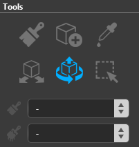
Fine Adjustment Tool (or press D ) |
| |
Multiple objects can be selected by holding down the Shift key when using these tools |
| Then .. |
|
|
Either:-
|
Press the Delete key, OR |
|
Open the Context Menu of the object (or object group) and select the Delete option
|
|
|
|
OR |
|
Use the Marquee Tool to select the object or a group of objects, then either:-
|
Press the Delete key OR |
|
Open the Marquee Context Menu and select the Delete option |
|
|
|
|
 |
Keyboard Shortcut: R |
The Eyedropper Tool identifies objects in a route |
| This tool uses the Assets Palette. If this palette is not visible on the screen then refer to Notes: Palettes at the top of this document.
|
|
The Eyedropper Tool has no drop down menu lists.
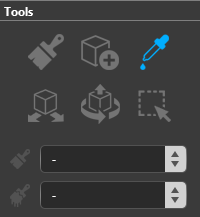 |
When selected, the Eyedropper Tool will change the mouse pointer to an "eyedropper" icon.
|
Quick Steps
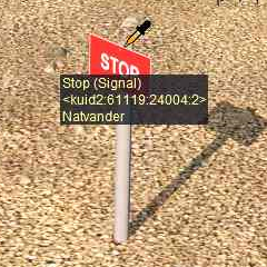
With the Eyedropper Tool selected, move the mouse pointer (which will now be an eyedropper symbol) onto any object in view.
 |
|
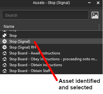
Left click on the object to identify it (highlighted in grey) in the Assets Palette filter list 
|
|
|
Left click on the object name in the Assets Palette filter list to select it (highlighted in blue) and switch control to the Placement Tool
 |
Narrowing the Search
Sometimes (or often) a scene will be too crowded with different scenery objects to be able to use the Eyedropper Tool to easily select a single object. In these cases additional options are available to help "remove the clutter".
|
These filter options can be used with asset selections when using the Placement Tool and the Marquee Tool as well as with the Eyedropper Tool |
|
At the top of the Assets Palette is a drop down box which controls how the Tool works with the filters that you set.
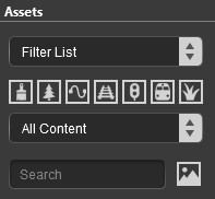 |
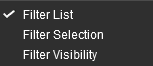
The drop down box will provide three options:-
|
Filter List |
|
Filter Selection |
|
Filter Visibility |
|
 |
|
These options work with the Asset Filters to help narrow the search for a specific object or type of object that is in the route.
| Filter List |
this option will have no effect on the operation of the Tool or on the objects displayed on the screen. It is the default setting and any selections made with the Tool will be shown in the Assets Palette as described in the section Quick Steps above. |
| Filter Selection |
this option will restrict the Tool to only working on those objects that are in the filtered list. Objects that are not in the filtered list cannot be selected. |
| Filter Visibility |
this option will hide all objects that are not in the filtered list. The only exceptions are Ground Textures and Effect Layers which will be visible but, unless they are also in the filtered list, cannot be selected. |
|
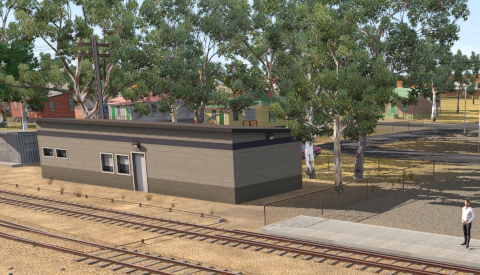
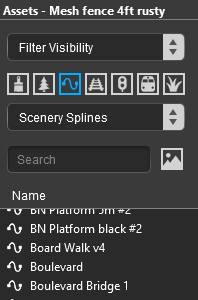
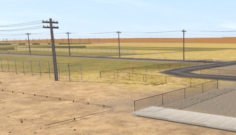
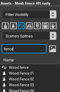
As an example the following images show the progressive application of a Visibility Filter.
 |
Keyboard Shortcut: S |
The Free Move Tool moves objects around a route |
| This tool uses the Tool Options Palette. If this palette is not visible on the screen then refer to Notes: Palettes at the top of this document.
|
|
The Free Move Tool has no drop down menu lists.
For Scenery Mesh Objects
Individual "non-spline" scenery objects that are not attached to track are often referred to in Trainz terminology as Scenery Mesh Objects.
Moving a Scenery Mesh Object
Set the Height for a Scenery Mesh Object
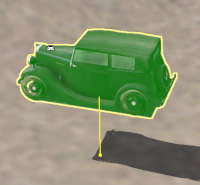
When placed in a route by the Placement Tool a scenery object will take the height of the terrain as its set height. It will be fixed to the terrain so when you move it around it will always be at the same height as the terrain it is over.
This can be changed to fix the object to a set height above or below the terrain.
 |
| Steps:To set the height of a Scenery Mesh Object:- |
|
With the scenery object selected, enter a height value into the Tool Options Height text box |
|
Hit the Enter key |
| The scenery object will now be fixed at the entered height above (or below) the terrain as it is moved around.
|
|
|
Mesh Object Context Menu
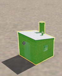
A selected scenery object, or a group of selected scenery objects, will have a Context Icon that opens a Context Menu. The icon design will vary between object types.
To open a selected objects Context menu either:-
|
Left click the Context Icon, OR |
 |
|
Press the T key |
|
|
Mesh Object Context Menu
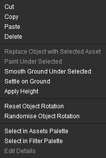 |
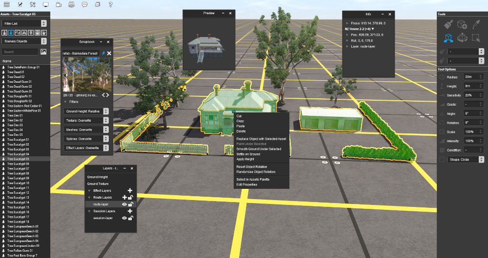
| Cut |
remove the selected object or objects and move them into the Scrapbook |
| Copy |
copy the selected object or objects and place them into the Scrapbook |
| Paste |
paste the contents of the current Scrapbook at the cursor (focus) point |
| Delete |
delete the selected objects. It has the same effect as pressing the Delete key |
| Replace Object with Selected Asset |
the highlighted object will be replaced with the asset currently selected in the Assets Palette |
| Paint Under Selected |
the texture selected in the Assets Palette will be painted under the highlighted object. The Tool Options for the Brush Tool (Radius and Sensitivity) will control how the texture is applied |
| Smooth Ground Under Selected |
changes the height of the terrain under the object to match the set height of the object. If multiple objects at different heights have been selected then the terrain height will be set to match the height of the lowest object |
| Settle on Ground |
sets the height of the objects to match the height of the terrain beneath them ("drops them back to earth") |
| Apply Height |
sets the height of the objects to the value in the Tool Options Height text box |
| Reset Object Rotation |
resets the rotation angle of the objects to their default values |
| Randomise Object Rotation |
applies a random rotation angle to each object |
| Select in Assets Palette |
identifies the selected object in the Asset Palette like the Eyedropper Tool |
| Edit Properties |
opens the Properties window of the selected object |
|
|
For Track Objects
Track Objects (signals, switches, speed signs, etc) are always attached to an existing track. They can be moved to new positions along the track and in Surveyor Classic that was the limit of their movement.
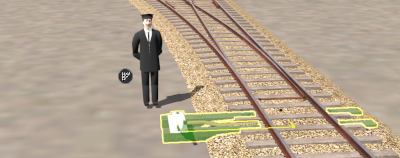
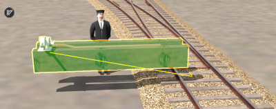
Surveyor 2.0 brings a new freedom of movement to track objects. They can be moved away from the track to the left or right as well as above and below the track. The operation of a track object is not affected by these changes.
The track object can still be moved along the track with the Free Move Tool.
Track Object Context Menu
To open a selected track objects Context menu either:-
|
Left click the Context Icon  OR |
|
Press the T key |
|
|
|
Track objects can be restored to their original height and position (on the track) by opening their Context Menu and selecting:-
|
Reattach to Track to cancel the both the height and position changes, OR |
|
Settle on Ground to cancel the height change only |
|
|
Track objects can also be rotated to the opposite side of the track.
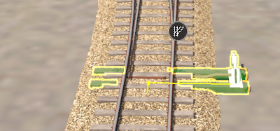 |
| Steps: To rotate a track object:- |
|
Open the track objects Context Menu (click the icon or press the T key) |
|
Select the option Rotate Trackside |
| Rotating a track object does not change its distance from the track or its height.
|
|
|
For Spline Objects (Including Track)
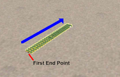
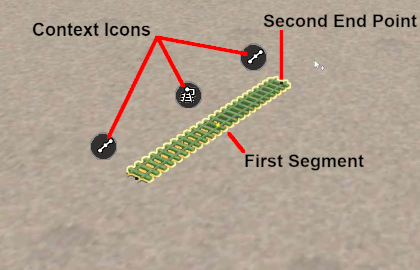
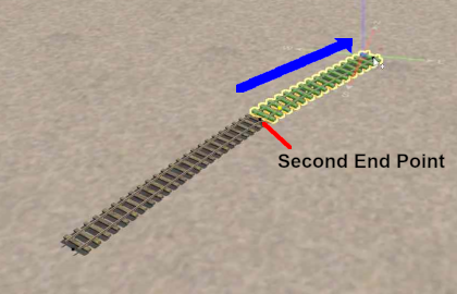
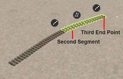
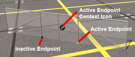
Scenery splines and track splines are defined by their endpoints. Splines are usually added to a route as a series of joined segments linked at the endpoints.
| Moving a spline can involve moving:- |
|
an endpoint, OR |
|
a segment, OR |
 |
multiple segments including the whole length of the spline |
|
Moving Spline Endpoints
Moving Spline Segments
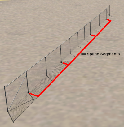
Splines are frequently made of multiple segments joined together. You can easily move a spline by moving its segments, individually or as a group.
 |
|
Not all splines have endpoints at each ends. As shown in the image on the left, some splines will have an "endcap" that is attached to the start of the first segment and to the end of the last segment. The use of an endcap is a purely cosmetic effect - to give the spline a more distinctive appearance.
|
|
|
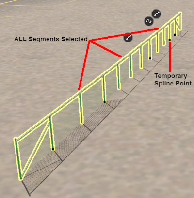 |
| IF you are going to select and move more than one spline segment, then:- |
|
hold the Shift key down and individually Left click between the endpoints on each additional segment.
The last segment that you click will have the temporary endpoint added. |
|
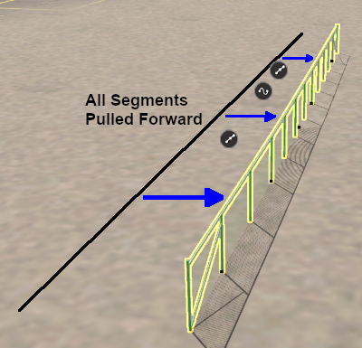
To select ALL the segments in a spline, Dbl-Left click on a segment
If the spline contains a junction then this will only select all the segments upto the junction point
The segment that you double-clicked will have the temporary endpoint added |
|
|
|
|
Use the mouse (Left button held down) to drag the selected segment(s) in any horizontal direction.
|
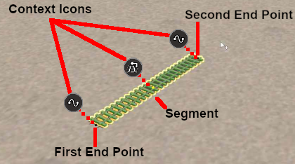
Spline Object Context Menu
 |
|
Notes: |
|
|
|
Left click on an icon to open its Context Menu.
 Endpoint Context Menu
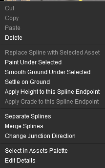 |
 Segment Context Menu
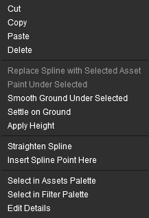 |
| Cut |
remove the segment or segments and move them into the Scrapbook |
| Copy |
copy the segment or segments and place them into the Scrapbook |
| Paste |
paste the contents of the current Scrapbook at the cursor (focus) point |
| Delete |
delete the segment, segments or endpoint. It has the same effect as pressing the Delete key |
| Replace Spline with Selected Asset |
the highlighted spline will be replaced with the asset currently selected in the Assets Palette |
| Paint Under Selected |
the texture selected in the Assets Palette will be painted under the highlighted spline segments. The Tool Options for the Brush Tool (Radius and Sensitivity) will control how the texture is applied |
| Smooth Ground Under Selected |
changes the height of the terrain under the segment or segments to match the set height of the spline (does not work on endpoints) |
| Settle on Ground |
sets the height of the segment, segments or endpoint to match the height of the terrain beneath them ("drops them back to earth"). When used on segments the spline will follow the height changes of the terrain |
| Apply Height (to this Spline Endpoint) |
sets the height of the segment, segments or endpoint to the value in the Tool Options Height text box |
| Apply Grade to this Spline Endpoint |
sets the height of the endpoint to give a Grade to the surrounding segments that matches the value in the Tool Options Grade text box |
| Straighten Spline |
forces a straight line (as far as possible) between the endpoints of a single segment. This option will be ticked if the segment has already been straightened in which case selecting this option will "un-straighten" the segment and remove the tick |
| Separate Splines |
breaks the spline into two separate splines at the endpoint |
| Merge Splines |
removes the selected endpoint and merges the segments on both sides into one segment. The two segments can also be joined by selecting and deleting the endpoint with the Delete key |
| Insert Spline Point Here |
inserts a new endpoint in a segment at the point where it was clicked. This will create a new segment at the endpoint |
| Select in Assets Palette |
identifies the selected spline in the Asset Palette like the Eyedropper Tool |
| Edit Properties |
opens the Properties window of the selected spline |
|
 |
Keyboard Shortcut: D |
The Fine Adjustment Tool makes 3D adjustments (position and rotations) to objects in a route |
| This tool uses the Tool Options Palette. If this palette is not visible on the screen then refer to Notes: Palettes at the top of this document.
|
|
The Fine Adjustment Tool has no drop down menu lists.
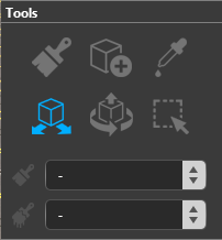
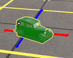
The most obvious feature of the Fine Adjustment Tool is the 3D Anchor Frame it adds to the selected object.
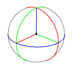 |
The coloured lines, called Anchors , allow manual positional and rotational controls:-
| The Horizontal and Vertical Anchors |
| Red Green Blue |
move the object (forward and back) in the direction of the Anchor |
| The Rotational Anchors |
| Red Green Blue |
rotate the object (clockwise and anti-clockwise) along the Anchor |
| Steps: To use the Fine Adjustment Tool controls:- |
|
move the mouse pointer onto an Anchor - its colour will change to white |
|
hold down the Left button |
|
drag the pointer along the chosen line in the direction required (e.g. Up or Down on the blue vertical Anchor) |
|
|
|
|
Notes:
Not all objects will have Red and/or Green rotational Anchors.
|
|
For Scenery Mesh Objects
Individual "non-spline" scenery objects that are not attached to track are often referred to in Trainz terminology as Scenery Mesh Objects .
You can move the objects freely in the horizontal plane by using a Left Click and Drag anywhere on the selected object except on an Anchor point or line.
To move an object in one of the Anchor directions, Left Click and Drag on an Anchor line.
Blue vertical Anchor movement
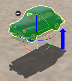 |
|
Green Anchor rotation
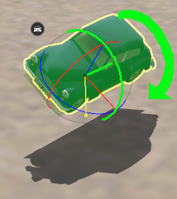 |
|
Red Anchor rotation
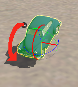 |
|
Blue Anchor rotation
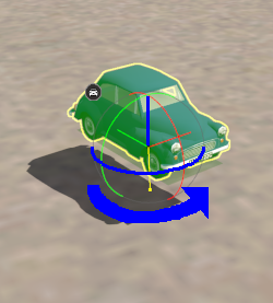 |
|
Notes:
Objects can be restored to their original height and rotation settings by opening their Context Menu and selecting either:-
|
Reset Object Rotation to cancel the rotation changes, OR |
|
Settle on Ground to cancel the height change |
The Randomise Object Rotation option in the Context Menu only affects rotations around the vertical axis.
|
|
|
Selecting Multiple Objects
Multiple objects can be selected with the Fine Adjustment Tool.
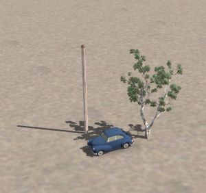
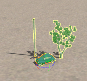
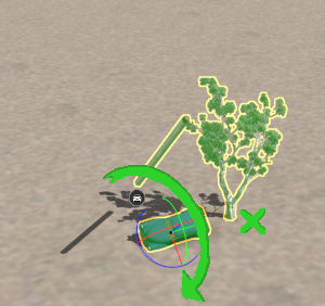
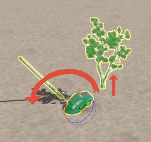
In the examples shown above, the car and the pole have no movement restrictions while the tree does not allow rotations through the Red and Green rotational Anchors.
The car was the last selected object so it has the Context Icon and the 3D Anchor Frame.
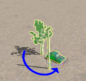 |
Using the Blue rotation Anchor, all the objects are rotated in the horizontal plane around the 3D Anchor Frame which is attached to the car, the last object that was selected. The 3D Anchor Frame on the car is the centre of all rotations. |
 |
Restarting from their original positions and using the Green rotation Anchor, the car and pole objects are rotated
through a horizontal plane which runs through the 3D Anchor Frame. Depending on its position in relation to the 3D Frame the tree may move vertically (but not rotate) or not move at all. |
 |
Again restarting from their original positions and using the Red rotation Anchor , the car and pole objects are rotated through a horizontal plane which runs through the 3D Anchor Frame. This time the tree does move (again depending on its position) but vertically upwards. It does not rotate like the car and the pole. |
Mesh Object Context Menu
|
| Cut |
remove the selected object or objects and move them into the Scrapbook |
| Copy |
copy the selected object or objects and place them into the Scrapbook |
| Paste |
paste the contents of the current Scrapbook at the cursor (focus) point |
| Delete |
delete the selected objects. It has the same effect as pressing the Delete key |
| Replace Object with Selected Asset |
the highlighted object will be replaced with the asset currently selected in the Assets Palette |
| Paint Under Selected |
the texture selected in the Assets Palette will be painted under the highlighted object. The Tool Options for the Brush Tool (Radius and Sensitivity) will control how the texture is applied |
| Smooth Ground Under Selected |
changes the height of the terrain under the object to match the set height of the object. If multiple objects at different heights have been selected then the terrain height will be set to match the height of the lowest object |
| Settle on Ground |
sets the height of the objects to match the height of the terrain beneath them ("drops them back to earth") |
| Apply Height |
sets the height of the objects to the value in the Tool Options Height text box |
| Reset Object Rotation |
resets the rotation angle of the objects to their default values |
| Randomise Object Rotation |
applies a random rotation angle to each object |
| Select in Assets Palette |
identifies the selected object in the Asset Palette like the Eyedropper Tool |
| Edit Properties |
opens the Properties window of the selected object |
|
|
For Track Objects
Track Objects (signals, switches, speed signs, etc) are always attached to an existing track. They can be moved to new positions along the track and in Surveyor Classic that was the limit of their movement.
Surveyor 2.0 brings a new freedom of movement to track objects. They can be moved away from the track to the left or right as well as above and below the track. The operation of a track object is not affected by these changes.
| Steps: To move a track object with the Fine Adjustment Tool |
|
For movements along the track - Left Click and Drag
|
|
For movements perpendicular to the track - Left Click and Drag
|
| For most track objects the Rotational Anchors have no effect |
|
Track Object Context Menu
To open a selected track objects Context menu either:-
|
Left click the Context Icon OR |
|
Press the T key |
|
|
|
Track objects can be restored to their original height and position (on the track) by opening their Context Menu and selecting:-
|
Reattach to Track to cancel the both the height and position changes, OR |
|
Settle on Ground to cancel the height change only |
|
|
Track objects can also be rotated to the opposite side of the track.
For Spline Objects (Including Track)
Scenery splines and track splines are defined by their endpoints. Splines are usually added to a route as a series of joined segments linked at the endpoints.
| Moving a spline can involve moving:- |
|
an endpoint, OR |
|
a segment, OR |
|
multiple segments including the whole length of the spline |
|
Moving Spline Endpoints
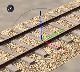 |
| Steps: To move an individual spline endpoint:- |
|
Select the Fine Adjustment Tool. |
|
Select, Left click on, the spline endpoint to be moved. |
| Note: only the horizontal Red and Green and the vertical Blue lines can be selected. |
|
Left Click and Drag either:-
|
an Anchor to move the endpoint in that specific direction, OR |
|
the endpoint itself to move it in any direction in the horizontal plane |
|
|
|
Moving Spline Segments
|
Notes: |
| |
The Green rotational Anchor CANNOT be used on Track splines
|
|
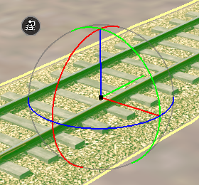 |
| Steps: To move spline segments:- |
|
Select the Fine Adjustment Tool. |
|
Select, Left click on, the spline segment to be moved. |
|
Left Click and Drag either:- |
| |
|
an Anchor to move the endpoint in that specific direction, OR |
|
anywhere in a segment to move it in any direction in the horizontal plane |
|
|
|
|
To select:-
|
more than one segment. Hold the Shift key down and individually Left click on each segment |
|
ALL the segments. Dbl-Left click on a segment. If the spline contains a junction then this will only select all the segments upto the junction point |
|
|
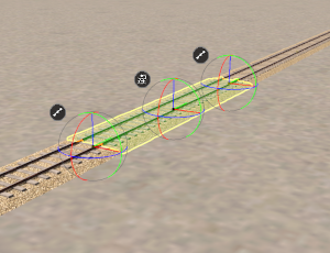 |
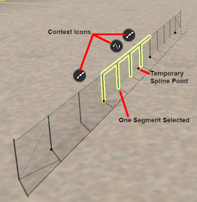
Selecting a spline segment with the Fine Adjustment Tool will add a Temporary Endpoint at the point where the segment was clicked.
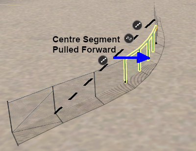
This will produce 3 Fine Adjustment Tool control frames, one at each end of the segment and one at the click point, as shown in the image on the left. The whole segment can be moved, as shown in the following images, by a Left Click and Drag anywhere within the segment. |
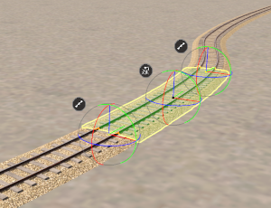
Segment moved to the right along the Red line |
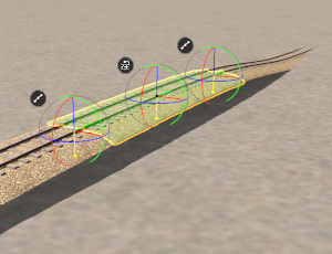
Segment moved up along the Blue line |
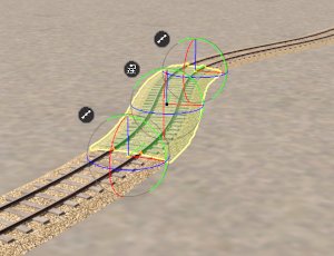
Segment rotated anti-clockwise around the Blue Anchor |
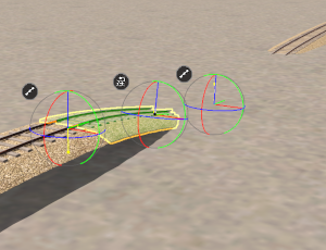
Segment rotated clockwise the Red Anchor |
|
 |
Keyboard Shortcut: F |
The Marquee Tool selects areas of a route |
| This tool uses the Scrapbook Palette and some features use the Assets Palette and the Tool Options Palette. If these palettes are not visible on the screen then refer to Notes: Palettes at the top of this document.
|
|
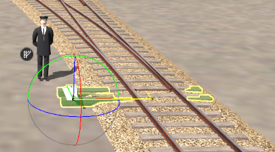
The Marquee Tool draws out a rectangular area on the route. Any objects (including Heights, Textures and Effect Layers) that are in the area or touched by the boundary of the Marquee area will be selected.
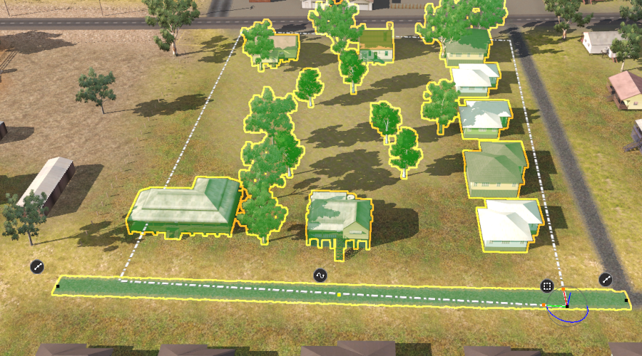
Not shown in the image, because they are not highlighted, are the Ground Heights, Ground Textures and Effect Layers inside the rectangle that are also included in the Marquee selection.
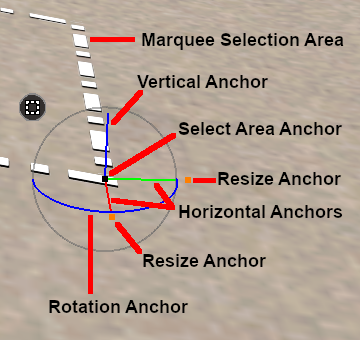 |
The Marquee Selection Area 3D Anchor Frame has some similarities to the one used with the Fine Adjustment Tool.
|
Marquee Anchor Controls
The following images demonstrate the effect of using the Marquee Anchor Controls on the image shown at the top of this section as the starting point.
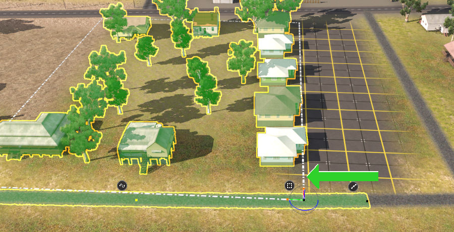
Horizontal Anchor Shift
| |
The Green horizontal Anchor has been used to shift the Marquee Selection Area to the left. Note that the 3 trees and a small building that were on the left of the Marquee Selection Area in the image above have been replaced (overwritten) by the Marquee contents. |
|
| |
 |
| |
|
Rotational Anchor Shift
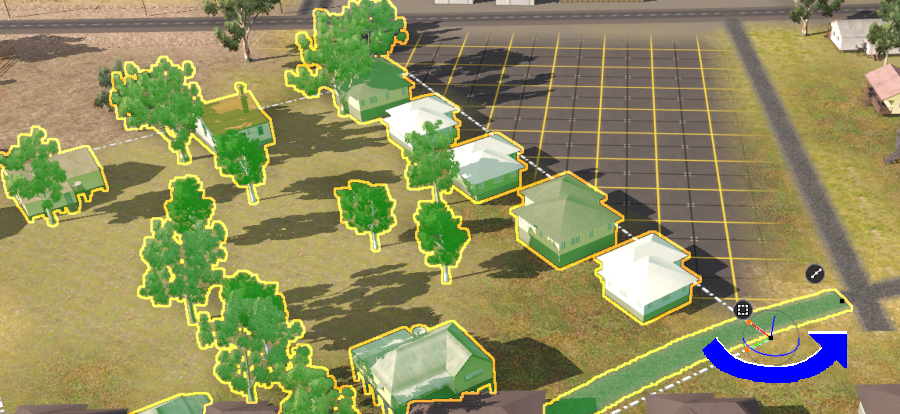
| |
The Blue rotational Anchor has been used to rotate the Marquee Selection Area about 45° anti-clockwise. Again, anything that was originally in the area now covered by the Marquee Selection Area has been replaced by the contents of the Marquee. |
|
| |
 |
| |
|
Vertical Anchor Shift
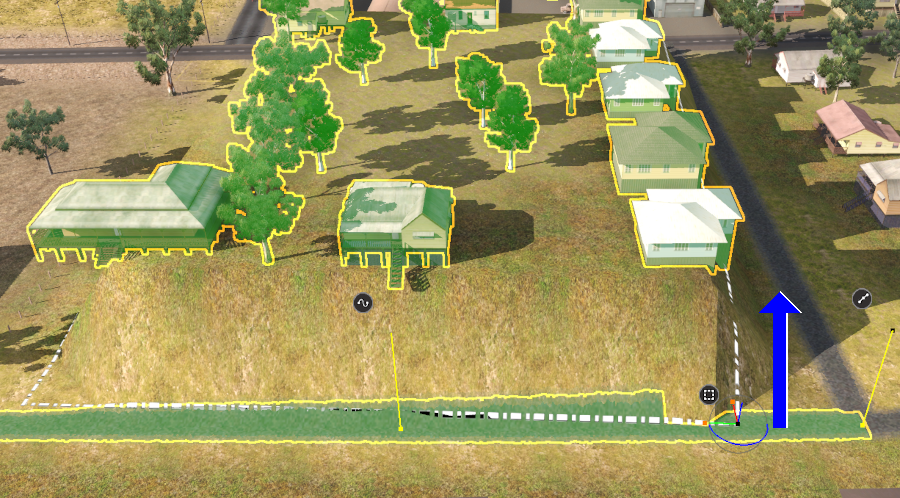
| |
The Blue vertictal Anchor has been used to lift the Marquee Selection Area upwards. |
|
| |
 |
| |
|
|
Notes:
|
|
|
Scrapbook Operations
Once an area has been marked out by the Marquee Tool a number of options become available.
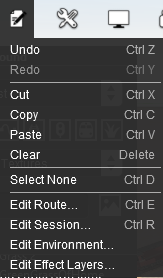 |
The Trainz Edit Menu will show some additional options:-
| Cut |
the objects selected in the Marquee area (including the ground heights, ground textures and effect layers) will be copied and placed into a new Scrapbook. Any scenery objects (excluding ground heights, ground textures and effect layers) that are not in a locked layer will be removed from the Marquee area. |
| Copy |
the objects selected in the Marquee area (including ground heights, ground textures and effect layers) will be copied and placed into a new Scrapbook. |
| Paste |
the contents of the current Scrapbook will be pasted into the route at the cursor (focus) point. Which contents will be pasted and how they will be pasted are controlled by the Filters in the Scrapbook Palette (see Scrapbook Data for more details). This option will always be available with and without a Marqee area being marked if there is a scrapbook available to be pasted. |
| Clear |
the selected scenery objects that are not in locked layers will be removed from the Marquee area but NOT the selected ground heights, ground textures and effect layers. |
| Select None |
the Marquee selection boundary lines are removed from the route cancelling the selection process. Everything else is left as it was. |
|
Left click on the Marquee Context Icon or press the T key to open the Context Menu for the Marquee.
Marquee Context Menu
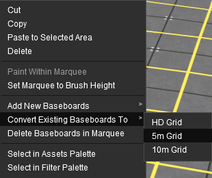 |
| Cut |
the objects selected in the Marquee area (including the ground heights, ground textures and effect layers) will be copied and placed into a new Scrapbook. Any scenery objects (excluding ground heights, ground textures and effect layers) that are not in a locked layer will be removed from the Marquee area. |
| Copy |
the objects selected in the Marquee area (including ground heights, ground textures and effect layers) will be copied and placed into a new Scrapbook. |
| Paste to Selected Area |
the contents of the current Scrapbook will be pasted into the Marquee area. Which contents will be pasted and how they will be pasted are controlled by the Filters in the Scrapbook Palette (see Scrapbook Data for more details). This option will always be available with and without a Marqee area being marked if there is a scrapbook available to be pasted. |
| Delete |
the selected scenery objects that are not in locked layers will be removed from the Marquee area but NOT the selected ground heights, ground textures and effect layers. |
|
| Paint Within Marquee |
the currently selected Ground Texture will be painted into the Marquee area using the Radius and Sensitivity settings in the Brush Tool Options. If no texture has been selected in the Assets Palette then this option will be greyed out. |
| Set Marquee to Brush Height |
the Ground Height in the Marquee area will be set using the Height setting in the Brush Tool Options. |
| Convert Baseboards To |
the entire baseboard where the Marquee selection area is located will be converted to a 5 metre or a 10 metre grid size (select one from the sub menu). The 5 metre grid gives a more accurate ground shape but it uses 4x as much memory. |
| Delete Baseboards in Marquee |
when a Marquee Selection Area is drawn inside a baseboard, the entire baseboard will be given a green border. If the Marquee is drawn over the boundary between basebaords then both will have a green border. This option will delete ALL the baseboards that have a green border. |
| Select in Assets Palette |
when a single asset has been highlighted, including ground textures and effect layers, this will identify the asset in the Assets Palette. |
The Info Palette
| If the Info Palette is not visible on the screen then refer to Notes: Palettes at the top of this document. Some Info Palette functions will also require the Assets Palette and the Tool Options Palette.
|
|
This palette can be easily overlooked but it has some very useful features.
The Info Palette will appear as shown in the image below.
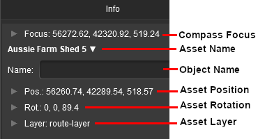 |
Each of the small arrowhead icons will open the palette to display more information and some controls. |
|
Notes:
All the positional data and controls in the Info Palette are defined in the following ways:-
|
|
Focus Info and Controls
The Focus shows the current position and height of the Cursor object. Open up the Focus by Left clicking on its arrowhead icon.
|
Before changing the cursor position with the Focus controls, set a Bookmark at its current position.
|
|
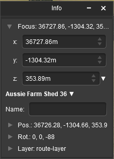 |
The current cursor position is shown in the X, Y and Z text boxes. These values can be edited to move the cursor to a new position but CARE will be needed.
|
Notes:
If you enter an X or Y value that is beyond the edge of a baseboard then the cursor will be refocussed at a point on the baseboard edge that is the closest to the entered co-ordinates.
|
|
On the right of each box is a pair of Up/Down controls. Left Click and Drag up or down on these to adjust the cursor position in smaller increments.
|
Next to the Z co-ordinate is a small down arrow. Left click on the arrow to open its menu.
 |
There is only one item in the sub-menu. Use Height for Brush
Left click on the option to copy the current cursor height (Z) value from the Info Palette to the Tool Options Palette Height entry. |
Asset Name Menu
You must have an object selected for its name to be shown and the menu options to be available.
 |
If more than one object has been selected then the name of the last selected object will be shown together with a count of additional selected objects (the named object (+2) indicating 2 additional objects shown in the image on the left). The position data shown will be for the last selected object. |
Next to the assets name co-ordinate is a small down arrow. Left click on the arrow to open its menu.
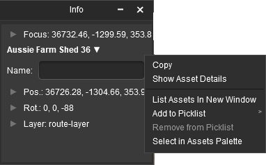 |
The menu options are:-
| Copy |
undescribed at present |
| Show Asset Details |
opens a new window showing the image and description of the selected asset |
| List Assets in New Window |
opens up Content Manager and lists all the selected assets |
| Add to Picklist |
adds selected assets to a Picklist |
| Remove from Picklist |
removes selected assets from a Picklist (assets must already be in a Picklist) |
| Select in Assets Palette |
highlights the selected asset in the Assets Palette |
|
Position Info and Controls
You must have an object selected for its position data to be shown and edited. Open up the object position data by Left clicking on its Pos: arrowhead icon.
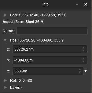 |
The position of the selected object (or the last object if more than one is selected) is shown in the X, Y and Z text boxes. These values can be edited to move the object or objects to a new position but CARE will be needed.
|
Notes:
If you enter an X or Y value that is beyond the edge of a baseboard then the objects will be moved to that position and may vanish from view. The Undo command can be used to reverse the move or the Marquee Tool can be used to add a baseboard under the "floating" objects. |
|
On the right of each box is a pair of Up/Down controls. Left Click and Drag up or down on these to adjust the position in smaller increments.
|
Next to the Z co-ordinate is a small down arrow. Left click on the arrow to open its menu.
 |
There is only one item in the sub-menu. Use Height for Brush
Left click on the option to copy the height (Z) value for the selected object from the Info Palette to the Tool Options Palette Height entry. |
Rotation Info and Controls
You must have an object selected for its rotation data to be shown and edited. Open up the object rotation data by Left clicking on its Rot: arrowhead icon.
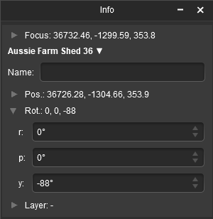 |
The rotational orientation of the selected object (or the last object if more than one is selected) is shown in the R, P and Y text boxes. These values can be edited to rotate the object or objects in 3D space BUT not all objects can be rotated in certain directions.
On the right of each box is a pair of Up/Down controls. Left Click and Drag up or down on these to adjust the rotation angle in smaller increments.
|
|
Notes:
The rotation data and controls are defined in the following ways:-
|
|
Layer Info and Controls
You must have an object selected for its layer data to be shown and edited. Open up the object layer data by Left clicking on its Layer: arrowhead icon.
|
Notes:
|
|
|
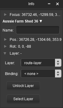 |
This will show the:-
|
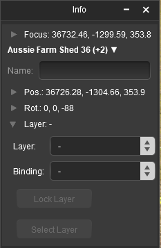 |
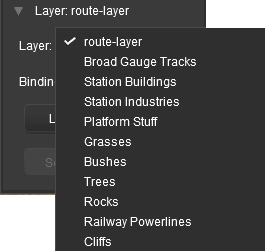
If multiple objects from different layers have been selected then no layer name will be shown in the Layer and Binding boxes. Instead they will be left "blank" as shown in the image on the left.
Both boxes can still be opened to assign layers to objects. |
Assigning Objects to a Different Layer
A selected object or group of selected objects can be assigned to a different layer. If multiple objects have been selected then they do not have to all be in the same layer.
Once a target layer has been selected then the Select Layer button, which sets the Active Layer, may become active.
The Active Layer is the layer used by the Placement Tool when objects are added to a route (or session). This button gives you the opportunity to set the Active Layer to the same layer that you just used to assign to an object. Its use is optional.
You can also set the Active Layer by selecting its name from the layer list in the Assets Palette.
| If the Select Layer button is greyed out |
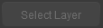 |
then the selected object is now assigned to the current Active Layer so there is no need to use this option |
| If it is NOT greyed out |
 |
then the selected object is now assigned to a layer that is not the current Active Layer. You have the option to Left click on this button to switch the Active Layer to the same layer as the object
|
|
Assigning Objects to a Binding Layer
The Binding Layer, or Bound Layer as it is also called, is a tool used in the development of a route or session.
It allows you to temporarily assign an object to a second layer while it is still in its original layer. The object will then take on the properties (Locked/Unlocked, Hidden/Visible) of both layers.
Some examples of using the Binding Layer:-
| Example 1: |
| The problem: |
You need to stop an object from being selected so that you can you move other objects on or around it |
| The solution: |
Set the Binding Layer of the object to a locked layer (or use the Assets Palette to create a new empty layer and lock it). The object will then be locked even though its original layer is unlocked so it cannot be selected or moved. When the edit has been completed, reset the object Binding Layer to <none> or delete the empty locked layer you just created |
| Example 2: |
| The problem: |
A group of objects (e.g trees) are blocking access to another object. |
| The solution: |
Set the Binding Layer of the blocking objects to a hidden layer (or use the Assets Palette to create a new empty layer and hide it). The blocking objects will no longer be visible even though their original layer is visible. When the edit has been completed, reset their Binding Layer to <none> or delete the empty hidden layer you just created
|
|
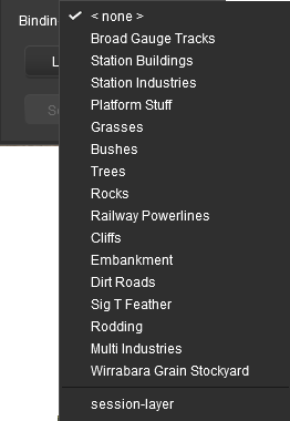 |
| Steps: To change the assigned binding layer of an object or group of objects:- |
|
Left click on the Binding drop down box. If the object is already bound to a layer (for a single selected object only) the binding layer will be shown with a in front of its name |
|
Select the Binding layer name from the drop down list |
| The layer reassignment will start the instant the layer is selected |
|
If you see a Debugging Window on the screen as the task is processed, it will inform you when the task has been completed. You can then close the window |
|
|
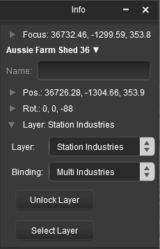
| As an example, the image below shows what you will see for a single object that has had:- |
 |
|
|
More information on creating, editing and using Layers can be found on the Trainz Wiki at:-
|
Trainz Wiki
 |
More Tutorials and Guides to Using Trainz
|
This page was created by Trainz user pware in January 2023 and was last updated as shown below.
|